


SOLIDWORKS Simulation generally provides reliable results once a part or assembly is set up correctly. However, challenges often arise when simulating assemblies, especially related to component interactions. In many cases, unexpected results occur because global interactions are either removed or the gap range for bonded contact is not defined correctly.
This blog explains bonded interaction with and without gap range in SOLIDWORKS Simulation using a practical assembly example.
Types of Component Interactions in SOLIDWORKS Simulation
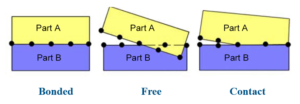
In the Component Interaction command window, SOLIDWORKS Simulation offers three interaction types:
- Bonded Interaction
Bonded interaction defines two faces as permanently connected. These faces may be:
- Directly touching, or
- Separated by a defined gap range
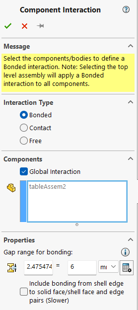
Once bonded, the faces remain connected regardless of the applied loads, and the components behave as a single body during analysis.
- Contact Interaction
Contact interaction allows faces to:
- Touch under load
- Separate when loads are removed
A small gap is permitted, enabling realistic movement between components. This interaction is commonly used for assemblies where sliding or separation is expected.
- Allow Penetration
This interaction allows components to penetrate each other during analysis. It is mainly used in:
- Frequency studies
- Buckling analysis
Understanding Gap Range in Bonded Interaction
The gap range defines the maximum allowable distance between faces for bonded interaction to be created. This is especially important when simulating assemblies that contain manufacturing clearances or modeling gaps.
Without specifying an appropriate gap range, SOLIDWORKS Simulation may fail to detect interactions between components.
Simulation Cases Considered
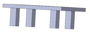
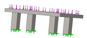
Case 1: Assembly Without Gap
- Components are in direct contact
- SOLIDWORKS Simulation automatically applies bonded interaction
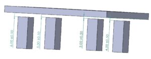
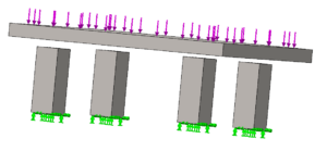
Case 2: Assembly With Gap
- Maximum gap between components: 6 mm
- No interaction is detected unless a gap range is specified
Boundary Conditions
- All four legs of the table are fixed
- A vertical load of 100 N is applied on the table top
Interaction Conditions and Behavior
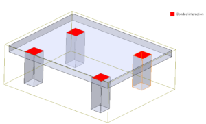
Case 1 – No Gap
- Geometry-based bonded interaction is automatically created
- Results show standard, expected structural behavior
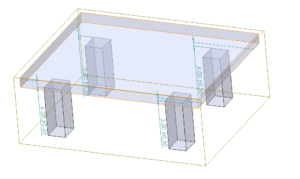
Case 2 – With Gap
- Initially, no geometry-based interaction is found
- When a gap range of 6 mm is defined, bonded interaction is successfully created.
Effect of Gap Range on Results
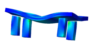
- Gap Range = 0 mm
- Interaction is not properly established
- Results show unrealistic behavior
- Gap Range = 6 mm
- Bonded interaction matches the physical assembly condition
- Results closely match Case 1
This clearly demonstrates that correct gap range definition is critical for accurate assembly simulation results.
Results Summary
- Assembly without gap: Stable and expected results
- Assembly with gap + correct gap range: Results match the no-gap case
- Assembly with gap but no gap range: Incorrect interaction and misleading results
Conclusion
When simulating assemblies in SOLIDWORKS Simulation, always verify:
- Component interaction type
- Presence of geometric gaps
- Proper gap range definition
Incorrect interaction settings can significantly affect simulation accuracy, even if boundary conditions and loads are correct.
Author Profile

Karthikeyan R is an Application Engineer with a B.E in Mechanical Engineering and an M.Tech in Product Design & Manufacturing. He has over 5 years of academic experience and 2.5+ years of industry experience in SIMULIA, SOLIDWORKS Simulation, and the 3DEXPERIENCE platform. He has successfully supported more than 50 customers in solving CAE challenges and improving product development outcomes.

