


Introduction
In SOLIDWORKS, managing multiple configurations of a part efficiently is essential for saving time and maintaining design accuracy. One of the most powerful tools for this purpose is the Design Table, which allows you to control dimensions, features, configurations, and materials directly from an integrated Microsoft Excel spreadsheet.
This blog explains how to create configurations using Design Tables in SOLIDWORKS, step by step, with practical insights for real-world design workflows.
What Is a Design Table in SOLIDWORKS?
A Design Table is an Excel-based table embedded inside a SOLIDWORKS part or assembly. It enables users to:
Create multiple configurations of the same model
Control dimensions and features parametrically
Apply complex equations using Excel formulas
Modify materials across configurations
System Requirement
To use Design Tables in SOLIDWORKS 2022–2025, Microsoft Excel 2016–2021 must be installed on the computer.
Design Table for Parts – Key Uses
Design Tables in parts are mainly used to:
Edit and control any dimension of a 3D part
Create multiple configurations from a single model
Apply advanced equations for automated design changes
This makes Design Tables ideal for families of parts, size variations, and standard components.
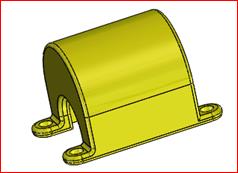
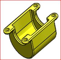
Step 1: Creating a SOLIDWORKS Part
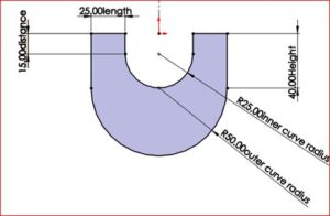
First, create a 3D part using SOLIDWORKS features such as sketches, extrudes, and fillets.
Assign specific names to dimensions
These names will later appear in the Design Table
Proper naming improves clarity and reduces errors
Step 2: Creating the Design Table
To insert a Design Table:
Menu Path:
Insert → Tables → Excel Design Table
Once selected, the PropertyManager opens with multiple options:
By default, Auto-create is selected
Auto-create generates a Design Table based on existing model dimensions
Click OK to proceed
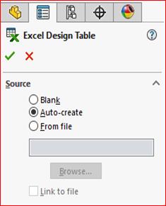
(Figure 3)
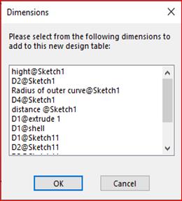
Step 3: Selecting Dimensions and Features
After choosing Auto-create:
A dialog box appears listing all available dimensions and features
Select the required parameters to include in the Design Table
Click OK
The selected dimensions are automatically loaded into the Excel Design Table.
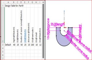
(Figure 4 & Figure 5)
Step 4: Modifying Dimensions and Features
Any change made inside the Design Table will immediately update the 3D model.
Examples:
Modifying D1@Fillet1 changes the fillet radius
Modifying D1@Boss-Extrude4 changes feature depth
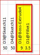

(Figure 6 & Figure 7)
This allows fast configuration control without manually editing features.
Step 5: Adding Configurations and Materials
Design Tables also support configuration and material management.
Key Capabilities:
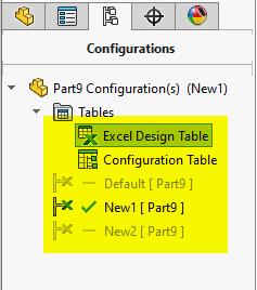
New configurations can be added directly in the table
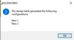
SOLIDWORKS notifies users when new configurations are created
Example configurations: New1, New2
Materials can be assigned per configuration using dropdown selections
After saving the Design Table:
SOLIDWORKS confirms the newly created configurations
Each configuration reflects the defined dimensions and materials
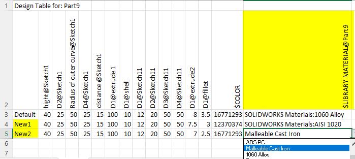
(Figure 8, Figure 9 & Figure 10)
Conclusion
Design Tables in SOLIDWORKS provide a powerful and efficient way to manage multiple configurations using Excel. By controlling dimensions, features, and materials from a single table, designers can significantly improve productivity and maintain consistent design intent. For engineers working with repetitive or parameter-driven designs, Design Tables are an essential tool.
About the Author

Sudhakar R
Application Engineer | Mechanical Engineering Specialist
With nearly two years of hands-on experience, Sudhakar specializes in SOLIDWORKS CAD and the 3DEXPERIENCE Design Ecosystem. He has supported over 100+ customers in product design, drafting, and 3D modeling, and conducts training sessions to help engineers and designers optimize SOLIDWORKS workflows using best practices. His passion lies in enabling teams to unlock the full potential of their design tools through efficient and automated processes.