
LOGOPRESS
Overview
Logopress – Advanced Die Design Solution with Blank Development, Strip Layout & Intelligent Tool Structure Capabilities
Logopress for SOLIDWORKS is a powerful die design and blank development solution that enables users to quickly determine theoretical blanks, create strip layouts, and design complete die structures with intelligent automation. It supports both native SOLIDWORKS models and imported CAD data without special preparation.
Designed primarily for the tool and die industry, it also extends to applications such as sheet metal, plastics, cloth, leather, adhesives, packaging, and inflatable objects. With advanced flattening, nesting, punch mounting, intelligent standard components, animation, interference detection, and finite element analysis capabilities, Logopress significantly reduces development time while increasing design accuracy and productivity across the entire die design process.
Core Functionalities
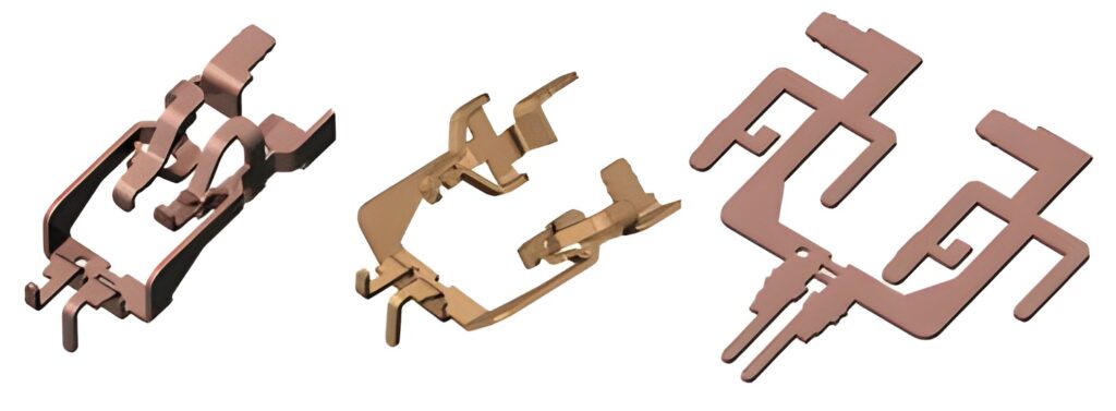
BLANK Prediction Function
Used for both progressive & transfer dies, it allows quick modelling of the true solid 3D strip stage by stage in an easy and logical way with fully parametric control.
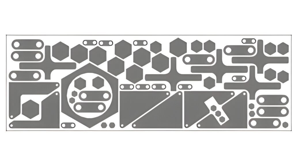
Strip Layout Module
Switch between full and partial unbending, edit angles, and refine unfolding at any design stage for precise output.
Strip Layout Design
Create true 3D progressive or transfer die strip layouts stage-by-stage with fully parametric control.
Nesting Module
Automatically nest multi-body parts or assemblies for efficient material usage and applications like EDM burn blocks and shims.
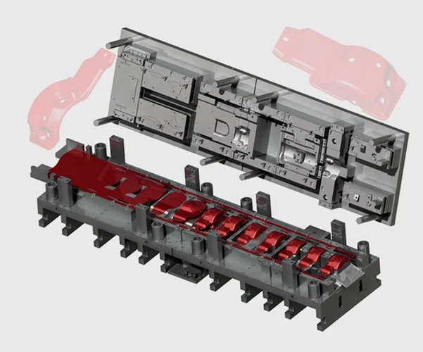
Die Set Assistant
Quickly build die structures, insert plates or sub-assemblies, define materials, heat treatments, and dimensions with ease.
Intelligent Standard Component Library
Insert standard components with automatic hole cutting and mate management across all plates.
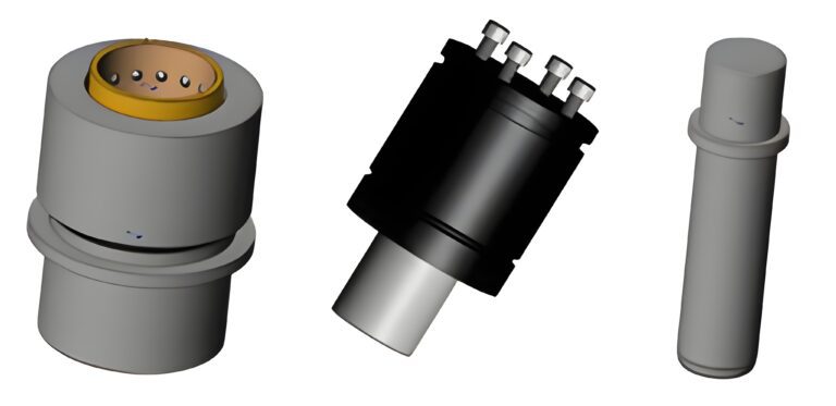
Punch Assistant & Insert Creation
Mount cutting, bending, and forming punches, create inserts and shims with automated preferences and minimal clicks.
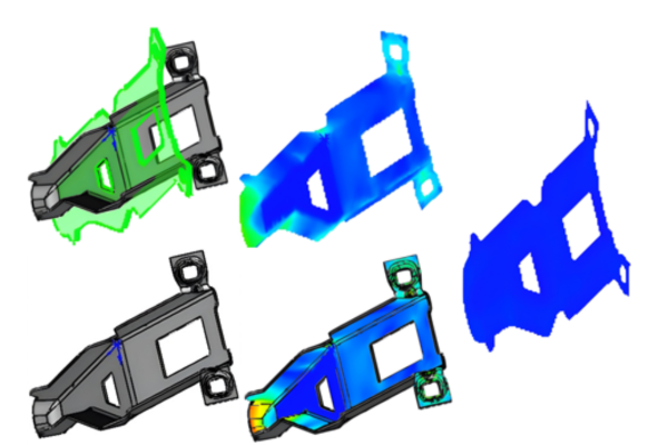
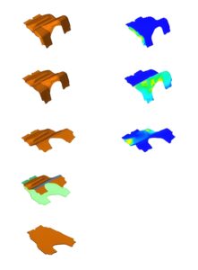
Animation & FEA Integration
Perform dynamic interference detection, collision checks, strip advancement simulation, and analyze thinning & springback using integrated finite element analysis.
Features
SOLIDWORKS Standard – Powerful 3D CAD for Efficient Product Design
- Allows the user to determine the theoretical blank of any 3D complex-shaped parts – especially Sheet Metal Parts quickly and easily.
- Parts can be imported as solid or surface models from any CAD system supported in SOLIDWORKS.
- Meshing for blank function is fully automatic and the size of the mesh can be adjusted/finetuned.
- K-Factors for each individual bend can be automatically calculated.
- Unfolding/unbending features can be edited at any point for precise output.
- Unfolding/unbending features can be edited at any point for precise output.
- Allows switching from full unbending to partial unbending.
- User can change partial unbending angle value, manage spring back options and bend allowance.
- Can be purchased independently or included inside the die design package.

SOLIDWORKS Standard – Powerful 3D CAD for Efficient Product Design
- Allows quick modelling of the true solid 3D strip stage by stage in a logical way.
- Can be started from a blank defined using Unbending and Flattening tools or from imported data.
- Includes specific features dedicated to Round Draw Parts.
- Fully parametric, allowing quick changes at any stage.
SOLIDWORKS Premium – Advanced Simulation & Motion for Complete Validation
- Starts with a multi-body part file or individual part files in an assembly.
- After setting logical parameters, quickly nests the parts as per user options.
- Useful when building Wire EDM burn blocks.
- Useful for nesting various shaped sharpening shims for under die inserts.
SOLIDWORKS Premium – Advanced Simulation & Motion for Complete Validation
- Includes Tool Structure Assistant to quickly model main die components.
- Allows insertion of additional plates or sub-assemblies.
- User can select and insert a plate or sub-assembly and adjust its dimensions.
- Plates can be named and material type and heat treatment can be specified at insertion.
- Intelligent Standard Component Library inserts selected components.
- Automatically cuts every hole in each plate and manages all mates.
SOLIDWORKS Premium – Advanced Simulation & Motion for Complete Validation
- Mounts cutting, bending, and forming punches and cuts all openings in all plates.
- Stores user preferences after defining the first mounting.
- Dedicated feature to create insert around punch or die mounting.
- Ability to automatically create a shim under the insert.
- Includes Intelligent Animation command.
- Automatically performs dynamic interference and collision detection between the four main sub-assemblies of the die.
- Shows entire die operating in the press including strip lifting and advancing with each press stroke.
SOLIDWORKS Premium – Advanced Simulation & Motion for Complete Validation
- Optional add-on requiring one of the Logopress software packages (BLANK, FLATTENING, STRIP LAYOUT or DIE DESIGN).
- Simplifies and speeds up modelling of intermediate stages.
- Allows forming a flat BLANK up to a complex shaped surface.
- Developed with complex mathematical algorithms after several years of research and development.
| Features |
|---|
|
SOLIDWORKS 3D CAD |
|
Part and Assembly Modelling |
|
Design Reuse and Automation |
|
Interference Check |
|
Collaborate and Share CAD Data |
|
Advanced CAD File Import/Export – 3D Interconnect |
|
First Pass Analysis Tools – Simulation Xpress |
|
Productivity Tools |
|
SOLIDWORKS CAM Standard* |
|
Design for Manufacturing |
|
Xtended Reality (XR) Exporter |
|
SOLIDWORKS Visualize Standard* |
|
CAD Libraries (SOLIDWORKS Toolbox) |
|
Design for Cost & Estimation (SOLIDWORKS Costing) |
|
ECAD/MCAD Collaboration (CircuitWorks™) |
|
CAD Standards Checking |
|
Automated Tolerance Stack-Up Analysis (TolAnalyst) |
|
SOLIDWORKS File Management |
|
Reverse Engineering (ScanTo3D) |
|
eDrawings® Professional |
|
Time – Based Motion Analysis |
|
Linear Static Analysis for Part and Assemblies |
|
Routing of Pipes and Tubes |
|
Routing of Rectangular and Other Sections |
|
Advanced Surface Flattening |
|
Assembly Level Cost Roll Up |
|
Electrical Routing |
| Standard |
|---|
|
|
|
|
|
|
|
|
|
|
|
|
|
|
|
|
|
|
|
|
|
|
|
|
|
|
|
|
|
|
|
|
|
|
|
|
|
|
|
|
|
|
|
|
|
|
|
|
|
|
|
|
|
|
| Professional |
|---|
|
|
|
|
|
|
|
|
|
|
|
|
|
|
|
|
|
|
|
|
|
|
|
|
|
|
|
|
|
|
|
|
|
|
|
|
|
|
|
|
|
|
|
|
|
|
|
|
|
|
|
|
|
|
| Premium |
|---|
|
|
|
|
|
|
|
|
|
|
|
|
|
|
|
|
|
|
|
|
|
|
|
|
|
|
|
|
|
|
|
|
|
|
|
|
|
|
|
|
|
|
|
|
|
|
|
|
|
|
|
|
|
|
Choosing the right SOLIDWORKS package depends on your design needs, team size, and project complexity.
From Standard to Premium, we help you identify the ideal solution that maximizes performance while staying within budget.
-
Want to buy
LOGOPRESS?
| Features |
|---|
|
SOLIDWORKS 3D CAD |
|
Part and Assembly Modelling |
|
Design Reuse and Automation |
|
Interference Check |
|
Collaborate and Share CAD Data |
|
Advanced CAD File Import/Export – 3D Interconnect |
|
First Pass Analysis Tools – Simulation Xpress |
|
Productivity Tools |
|
SOLIDWORKS CAM Standard* |
|
Design for Manufacturing |
|
Xtended Reality (XR) Exporter |
|
SOLIDWORKS Visualize Standard* |
|
CAD Libraries (SOLIDWORKS Toolbox) |
|
Design for Cost & Estimation (SOLIDWORKS Costing) |
|
ECAD/MCAD Collaboration (CircuitWorks™) |
|
CAD Standards Checking |
|
Automated Tolerance Stack-Up Analysis (TolAnalyst) |
|
SOLIDWORKS File Management |
|
Reverse Engineering (ScanTo3D) |
|
eDrawings® Professional |
|
Time – Based Motion Analysis |
|
Linear Static Analysis for Part and Assemblies |
|
Routing of Pipes and Tubes |
|
Routing of Rectangular and Other Sections |
|
Advanced Surface Flattening |
|
Assembly Level Cost Roll Up |
|
Electrical Routing |
| Standard |
|---|
|
|
|
|
|
|
|
|
|
|
|
|
|
|
|
|
|
|
|
|
|
|
|
|
|
|
|
|
|
|
|
|
|
|
|
|
|
|
|
|
|
|
|
|
|
|
|
|
|
|
|
|
|
|
| Professional |
|---|
|
|
|
|
|
|
|
|
|
|
|
|
|
|
|
|
|
|
|
|
|
|
|
|
|
|
|
|
|
|
|
|
|
|
|
|
|
|
|
|
|
|
|
|
|
|
|
|
|
|
|
|
|
|
| Premium |
|---|
|
|
|
|
|
|
|
|
|
|
|
|
|
|
|
|
|
|
|
|
|
|
|
|
|
|
|
|
|
|
|
|
|
|
|
|
|
|
|
|
|
|
|
|
|
|
|
|
|
|
|
|
|
|
Services & Training
We help you solve engineering challenges, together.
Whether you’re looking to outsource expertise or upskill your team, we work as a seamless extension of your organization to deliver measurable results.
Engineering Services
We help turn complex ideas into manufacturable products through robust design, analysis, and engineering support—focused on accuracy, efficiency, and real-world performance.
SOLIDWORKS Training
Develop practical SOLIDWORKS skills with flexible training programs designed for engineers, designers, and teams—covering essentials through advanced workflows.
FAQ
2D CADs are mainly used to create detailing and drafting whereas SOLIDWORKS helps in designing and developing in 3D which helps in better visual understanding. It also helps to create drafting and detailed manufacturing drawings.
Yes, SOLIDWORKS Supports the import of Other 3D CAD Files such as Autodesk Inventor, Pro/ENGINEER and Creo Parametric, Solid Edge, Unigraphics. It also supports the import of Neutral Files such as IGES/IGS, STEP, Parasolid, etc.
SOLIDWORKS Files
SOLIDWORKS Files (*.sldprt; *.sldasm)
SOLIDWORKS Assembly (*.asm; *.sldasm)
SOLIDWORKS Drawing (*.drw; *.slddrw)
SOLIDWORKS Part (*.prt; *.sldprt)
SOLIDWORKS SLDXML (*.sldxml)
Other Supported Formats
3D Manufacturing Format (*.3mf)
ACIS (*.sat; *.sab; *.asat; *.asab)
Add-Ins (*.dll)
Adobe Illustrator Files (*.ai)
Adobe Photoshop Files (*.psd)
Autodesk AutoCAD Files (*.dwg; *.dxf)
Autodesk Inventor Files (*.ipt; *.iam)
CADKEY (*.prt; *.ckd)
CATIA Graphics (*.cgr)
CATIA V5 (*.catpart; *.catproduct)
Interoperability & Exchange Formats
IDF (*.emn; *.brd; *.bdf; *.idb)
IFC 2x3 (*.ifc)
IGES (*.igs; *.iges)
JT (*.jt)
Library Feature Part (*.lfp; *.sldlfp)
Mesh Files (*.stl; *.obj; *.off; *.ply; *.ply2)
Parasolid (*.x_t; *.x_b; *.xmt_txt; *.xmt_bin)
PTC Creo Files (*.prt; *.asm; *.xpr)
Rhino (*.3dm)
Solid Edge Files (*.par; *.psm; *.asm)
STEP AP203 / AP214 / AP242 (*.step; *.stp)
Template Files (*.prtdot; *.asmdot; *.drwdot)
Unigraphics / NX (*.prt)
VDAFS (*.vda)
VRML (*.wrl)
Starting from SOLIDWORKS 2017, 3D Interconnect replaces SOLIDWORKS’ current translation capabilities with new technology and workflows for working with third-party native CAD data.
You can:
a. Insert proprietary CAD data directly into a SOLIDWORKS assembly without converting it to a SOLIDWORKS file.
b. Open the proprietary 3D CAD format in the SOLIDWORKS software with its associative link to the original part.
c. Update changes in the SOLIDWORKS file if you update the proprietary CAD data in its authoring application by maintaining all downstream features created in SOLIDWORKS.
d. Break the link of the inserted part file with the original part file. With the technology, you can work with other 3D CAD in the same native format without the need for translation to SOLIDWORKS Files.
Yes, SOLIDWORKS Drawings can be exported to DXF/DWG formats to open in 2D CAD software such as Draftsight, AutoCAD, etc.
No, It is not necessary to install SOLIDWORKS unless you want to make changes to the models.
For anyone who needs to view and interrogate 3D design data. Whether you are involved in the commercial manufacture, purchasing, a maker, or a student, eDrawings helps you to communicate, share and collaborate with 3D data with an easily shareable lightweight file in its own viewer.
Yes, SOLIDWORKS allows to import of 2D CAD Files such as DXF and DWG files and 3D Models can be created using the 2D views from DXF/DWG files as a reference inside the SOLIDWORKS environment.
The FeatureWorks software in SOLIDWORKS recognizes features on an imported solid body in a SOLIDWORKS part document. Recognized features are the same as features that you create using the SOLIDWORKS software. You can edit the definition of recognized features to change their parameters. For features that are based on sketches, after you recognize the features, you can edit the sketches from the SOLIDWORKS FeatureManager design tree to change the geometry of the features. However, it should be noted that not all features are recognized by Feature Works. Some geometry may not be recognized due to complexity.
SOLIDWORKS Comes with an Inbuilt material library that includes Steel, Iron, Aluminium, Copper, Titanium, Zinc, Plastics, non – Metals such as Air, Water, Rubber, Wood, etc.
All the materials include mechanical properties such as Elastic Modulus, Tensile Strength, Mass Density, Yield Strength, Thermal Conductivity, etc.
SOLIDWORKS is an easy-to-use intuitive user interface software. Along with part, assembly, and 2D drawing functionality, specialized tools are included sheet metal, weldments, surfacing, molds, product configuration, etc.
Yes, SOLIDWORKS has a portfolio of Simulation solutions that are integrated directly inside the SOLIDWORKS 3D Modeling environment. SOLIDWORKS Simulation is an easy-to-use portfolio of structural analysis tools that use Finite Element Analysis (FEA) to predict a product’s real-world physical behavior by virtually testing CAD models. The portfolio provides linear, non-linear static, and dynamic analysis capabilities which can be purchased as per requirements and integrated with SOLIDWORKS.