
SOLIDWORKS Inspection
Overview
SOLIWORKS - Powerful 3D CAD with Built-in Simulation, PDM, PLM Cababilities.
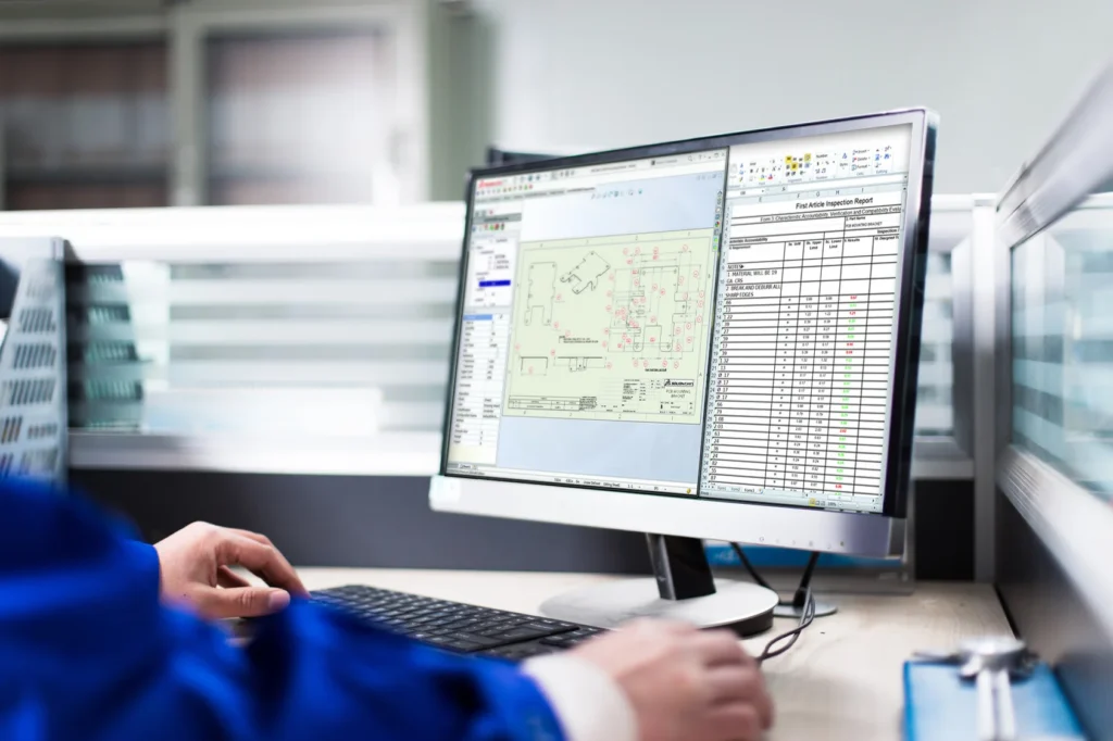
SOLIDWORKS Inspection Software is a First Article Inspection (FAI) and In-Process Inspection software that helps streamline creation of Quality Inspection documents with balloon callouts and specifications. By leveraging existing 2D (AutoCAD, DXF, DWG) legacy data in the form of SOLIDWORKS files, PDF and TIFF formats, it automates the creation of ballooned Inspection Drawings and Inspection Reports.
It is useful for Automotive companies and Product Engineering Teams to enable meeting the Advanced Product Quality Planing (APQP Standard Documentation). Inspection Software helps users meet ISO 2768, AS 9102 Compliance. CMM (Coordinate Measuring Machine) users will find the automated Inspection Process, saving time and effort for Part Quality Inspection and Acceptance.
SOLIDWORKS Inspection allows to enter measured inspection values directly either manually or automatically, using a digital measuring instrument (such as a USB caliper) or by importing coordinate measuring machine (CMM) results.
Core Functionalities
Stand-Alone Application
Use the stand-alone application or the SOLIDWORKS add-in to quickly balloon engineering drawings and create inspection reports.
Work with Multiple File Formats
Work with SOLIDWORKS drawing files, PDFs or TIFFs.
Automatic Ballooning
Automatically balloon Inspection Dimensions specified by the user.
OCR Data Capture
When working with PDF and TIFF files, capture inspection data using Optical Character Recognition (OCR).
Drawing Revision Comparison
Compare drawing revision to quickly identify changes.
Export & Reporting Options
Instantly export finished ballooned drawings as a PDF and export inspection reports to Excel spreadsheets using standard templates.
CMM & Measurement Integration
Enter measured values manually or via digital caliper and import CMM results directly into the project.
Tolerance Highlighting & Export
Highlight dimensions in Green, Red, and Yellow to instantly view tolerance status and export inspection data to quality systems via CSV or XML.
Features

Automated Inspection Documentation & Ballooning Solution
- First Article Inspection (FAI) and In-Process Inspection software
- Streamline creation of Quality Inspection documents with balloon callouts and specifications
- Leverage existing 2D (AutoCAD, DXF, DWG) legacy data in the form of SOLIDWORKS files, PDF and TIFF formats
- Automates the creation of ballooned Inspection Drawings and Inspection Reports
- Capture inspection data from PDF and TIFF files using Optical Character Recognition (OCR)
- Compare drawing revision to quickly identify changes
- Instantly export finished ballooned drawings as a PDF
- Export inspection reports to Excel spreadsheets using standard templates
- Customize Excel templates using the Template Editor to follow company or industry standards
- Export inspection data directly to quality systems and databases using CSV or XML output formats

Advanced Quality Inspection with CMM & Measurement Integration
- Enter measured inspection values directly either manually or automatically
- Use a digital measuring instrument (such as a USB caliper)
- Import Coordinate-Measuring Machine (CMM) results
- CMM users benefit from an automated Inspection Process for Part Quality Inspection and Acceptance
- Highlight dimensions in Green, Red and Yellow to instantly see In Tolerance, Out of Tolerance or Marginally within Tolerance
- Export color-coded ballooned drawings and inspection reports
- Create Inspection documents faster – Up to 90% Time Saving
- Streamline the creation of inspection documentation
- Reduce manual errors and inconsistencies
- Improve product quality and reliability
- Reduce rework during changes in design and drawings
- Reduce Time-to-Market
- Advanced Quality Inspection with CMM & Measurement Integration
| Features |
|---|
|
SOLIDWORKS 3D CAD |
|
Part and Assembly Modelling |
|
Design Reuse and Automation |
|
Interference Check |
|
Collaborate and Share CAD Data |
|
Advanced CAD File Import/Export – 3D Interconnect |
|
First Pass Analysis Tools – Simulation Xpress |
|
Productivity Tools |
|
SOLIDWORKS CAM Standard* |
|
Design for Manufacturing |
|
Xtended Reality (XR) Exporter |
|
SOLIDWORKS Visualize Standard* |
|
CAD Libraries (SOLIDWORKS Toolbox) |
|
Design for Cost & Estimation (SOLIDWORKS Costing) |
|
ECAD/MCAD Collaboration (CircuitWorks™) |
|
CAD Standards Checking |
|
Automated Tolerance Stack-Up Analysis (TolAnalyst) |
|
SOLIDWORKS File Management |
|
Reverse Engineering (ScanTo3D) |
|
eDrawings® Professional |
|
Time – Based Motion Analysis |
|
Linear Static Analysis for Part and Assemblies |
|
Routing of Pipes and Tubes |
|
Routing of Rectangular and Other Sections |
|
Advanced Surface Flattening |
|
Assembly Level Cost Roll Up |
|
Electrical Routing |
| Standard |
|---|
|
|
|
|
|
|
|
|
|
|
|
|
|
|
|
|
|
|
|
|
|
|
|
|
|
|
|
|
|
|
|
|
|
|
|
|
|
|
|
|
|
|
|
|
|
|
|
|
|
|
|
|
|
|
| Professional |
|---|
|
|
|
|
|
|
|
|
|
|
|
|
|
|
|
|
|
|
|
|
|
|
|
|
|
|
|
|
|
|
|
|
|
|
|
|
|
|
|
|
|
|
|
|
|
|
|
|
|
|
|
|
|
|
| Premium |
|---|
|
|
|
|
|
|
|
|
|
|
|
|
|
|
|
|
|
|
|
|
|
|
|
|
|
|
|
|
|
|
|
|
|
|
|
|
|
|
|
|
|
|
|
|
|
|
|
|
|
|
|
|
|
|
Choosing the right SOLIDWORKS package depends on your design needs, team size, and project complexity.
From Standard to Premium, we help you identify the ideal solution that maximizes performance while staying within budget.
-
Want to buy
SOLIDWORKS Inspection?
Services & Training
We help you solve engineering challenges, together.
Whether you’re looking to outsource expertise or upskill your team, we work as a seamless extension of your organization to deliver measurable results.
Engineering Services
We help turn complex ideas into manufacturable products through robust design, analysis, and engineering support—focused on accuracy, efficiency, and real-world performance.
SOLIDWORKS Training
Develop practical SOLIDWORKS skills with flexible training programs designed for engineers, designers, and teams—covering essentials through advanced workflows.
FAQ
2D CADs are mainly used to create detailing and drafting whereas SOLIDWORKS helps in designing and developing in 3D which helps in better visual understanding. It also helps to create drafting and detailed manufacturing drawings.
Yes, SOLIDWORKS Supports the import of Other 3D CAD Files such as Autodesk Inventor, Pro/ENGINEER and Creo Parametric, Solid Edge, Unigraphics. It also supports the import of Neutral Files such as IGES/IGS, STEP, Parasolid, etc.
SOLIDWORKS Files
SOLIDWORKS Files (*.sldprt; *.sldasm)
SOLIDWORKS Assembly (*.asm; *.sldasm)
SOLIDWORKS Drawing (*.drw; *.slddrw)
SOLIDWORKS Part (*.prt; *.sldprt)
SOLIDWORKS SLDXML (*.sldxml)
Other Supported Formats
3D Manufacturing Format (*.3mf)
ACIS (*.sat; *.sab; *.asat; *.asab)
Add-Ins (*.dll)
Adobe Illustrator Files (*.ai)
Adobe Photoshop Files (*.psd)
Autodesk AutoCAD Files (*.dwg; *.dxf)
Autodesk Inventor Files (*.ipt; *.iam)
CADKEY (*.prt; *.ckd)
CATIA Graphics (*.cgr)
CATIA V5 (*.catpart; *.catproduct)
Interoperability & Exchange Formats
IDF (*.emn; *.brd; *.bdf; *.idb)
IFC 2x3 (*.ifc)
IGES (*.igs; *.iges)
JT (*.jt)
Library Feature Part (*.lfp; *.sldlfp)
Mesh Files (*.stl; *.obj; *.off; *.ply; *.ply2)
Parasolid (*.x_t; *.x_b; *.xmt_txt; *.xmt_bin)
PTC Creo Files (*.prt; *.asm; *.xpr)
Rhino (*.3dm)
Solid Edge Files (*.par; *.psm; *.asm)
STEP AP203 / AP214 / AP242 (*.step; *.stp)
Template Files (*.prtdot; *.asmdot; *.drwdot)
Unigraphics / NX (*.prt)
VDAFS (*.vda)
VRML (*.wrl)
Starting from SOLIDWORKS 2017, 3D Interconnect replaces SOLIDWORKS’ current translation capabilities with new technology and workflows for working with third-party native CAD data.
You can:
a. Insert proprietary CAD data directly into a SOLIDWORKS assembly without converting it to a SOLIDWORKS file.
b. Open the proprietary 3D CAD format in the SOLIDWORKS software with its associative link to the original part.
c. Update changes in the SOLIDWORKS file if you update the proprietary CAD data in its authoring application by maintaining all downstream features created in SOLIDWORKS.
d. Break the link of the inserted part file with the original part file. With the technology, you can work with other 3D CAD in the same native format without the need for translation to SOLIDWORKS Files.
Yes, SOLIDWORKS Drawings can be exported to DXF/DWG formats to open in 2D CAD software such as Draftsight, AutoCAD, etc.
No, It is not necessary to install SOLIDWORKS unless you want to make changes to the models.
For anyone who needs to view and interrogate 3D design data. Whether you are involved in the commercial manufacture, purchasing, a maker, or a student, eDrawings helps you to communicate, share and collaborate with 3D data with an easily shareable lightweight file in its own viewer.
Yes, SOLIDWORKS allows to import of 2D CAD Files such as DXF and DWG files and 3D Models can be created using the 2D views from DXF/DWG files as a reference inside the SOLIDWORKS environment.
The FeatureWorks software in SOLIDWORKS recognizes features on an imported solid body in a SOLIDWORKS part document. Recognized features are the same as features that you create using the SOLIDWORKS software. You can edit the definition of recognized features to change their parameters. For features that are based on sketches, after you recognize the features, you can edit the sketches from the SOLIDWORKS FeatureManager design tree to change the geometry of the features. However, it should be noted that not all features are recognized by Feature Works. Some geometry may not be recognized due to complexity.
SOLIDWORKS Comes with an Inbuilt material library that includes Steel, Iron, Aluminium, Copper, Titanium, Zinc, Plastics, non – Metals such as Air, Water, Rubber, Wood, etc.
All the materials include mechanical properties such as Elastic Modulus, Tensile Strength, Mass Density, Yield Strength, Thermal Conductivity, etc.
SOLIDWORKS is an easy-to-use intuitive user interface software. Along with part, assembly, and 2D drawing functionality, specialized tools are included sheet metal, weldments, surfacing, molds, product configuration, etc.
Yes, SOLIDWORKS has a portfolio of Simulation solutions that are integrated directly inside the SOLIDWORKS 3D Modeling environment. SOLIDWORKS Simulation is an easy-to-use portfolio of structural analysis tools that use Finite Element Analysis (FEA) to predict a product’s real-world physical behavior by virtually testing CAD models. The portfolio provides linear, non-linear static, and dynamic analysis capabilities which can be purchased as per requirements and integrated with SOLIDWORKS.