EGS INDIA

+91 9445431704

info@egs.co.in

Authorized SOLIDWORKS RESELLER in Chennai, Coimbatore, Trichy

EGS INDIA

+91 9445424704

info@egs.co.in

Authorized SOLIDWORKS RESELLER in Chennai, Coimbatore, Trichy

EGS INDIA

+91 9445424704

info@egs.co.in

Authorized SOLIDWORKS RESELLER in Chennai, Coimbatore, Trichy

How Do You Create a SOLIDWORKS CAM User Defined Tool?

Introduction

A lot of companies that make things use cutting tools to do certain jobs that the regular tools in SOLIDWORKS CAM cannot do. The User Defined Tool feature in SOLIDWORKS CAM lets you make these tools add them to the Technology Database and then use them to make sure the machines cut the right way.

This guide will show you how to make a User Defined Tool in SOLIDWORKS CAM how to set it up and how to use it. You will learn how to use the User Defined Tool, in SOLIDWORKS CAM to get the toolpath for your machining jobs.

User Defined Tool

1.Design the tool in SOLIDWORKS part modelling.

2.Save the file as mill tool type (.mt) by clicking Tools>SOLIDWORKS CAM> User Defined Tools and Holders
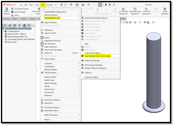
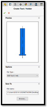
SOLIDWORKS CAM User Defined Tool

3.Save the file in local disk.

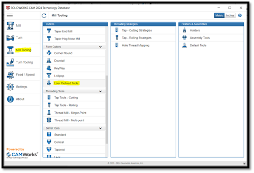
4.Open Technology Database on SOLIDWORKS CAM and select the User Defined Tools under Mill Tooling.

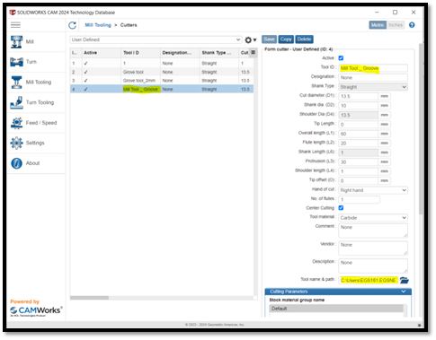
5.Under User Defined tools copy the default tool and change the parameters of the tools which we created earlier & map the location the mill tool file (.mt).

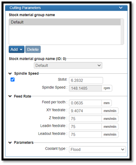
6.Add the Cutting parameters & save, now your are ready to use on the custom Marching operation with user defined tool.

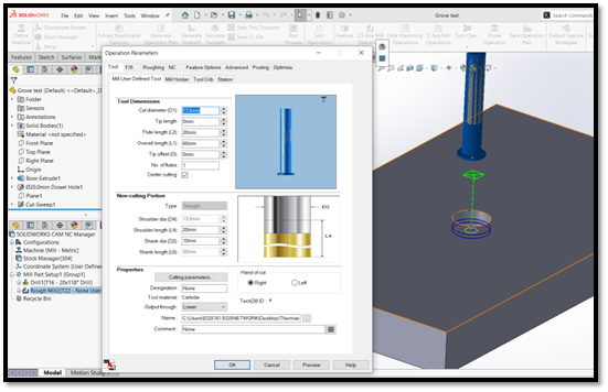
7.Here you can able to see the specific marching operation done with the User defined tool.

Author
sakthivel

About Sakthivel A


“Sakthivel A is an Team Leader-Technical Support at EGS Computers India Pvt Ltd, specializing in supporting and delivering value-added services to a diverse range of SOLIDWORKS customers for the past 4 years. He excels in understanding customer requirements and providing customized solutions to meet their needs effectively.”

Scroll to Top